
 |
 |
 |
 |
 |
Artigo
| Efficient treatment of NiII-citric acid complexes in nickel plating effluent using electrocatalytic oxidation-synergistic electrodeposition method and nickel resource recovery |
|
Bingzhao CuiI I. School of Environmental and Chemical Engineering, Chongqing Three Gorges University, 404100 Wanzhou, China Received: 03/20/2025 *e-mail: xinghu2200@163.com; 348815047@qq.com; 190732011@qq.com The chemical nickel plating process generates large volumes of wastewater. This wastewater contains NiII-citric acid complexes (Ni-Cit) that are difficult to treat. This study addressed the challenging Ni-Cit waste streams, focusing on development and implementation of a highly efficient and stable single-compartment approach for nickel recovery through electrocatalytic oxidation in synergistic electrodeposition. Our findings demonstrate that high-purity nickel (Ni) may be successfully recovered from Ni-Cit waste streams by combining electrocatalytic oxidation and electrodeposition. Scanning electron microscopy (SEM), X-ray diffraction (XRD), energy dispersive spectroscopy (EDS), and X-ray photoelectron spectroscopy (XPS) techniques were utilized to thoroughly examine the nickel recovered from the cathode. The study found that optimal electrochemical treatment was achieved with a current density of 100 mA cm-2, an initial pH of 4.05, and an initial Ni ion concentration of 0.01 M. Ni healing was achieved in 100% of cases after two hours of treatment. By investigating the degradation process of nickel waste solution complexed with citric acid, we proposed the mechanism of Ni-Cit electrocatalytic oxidation for complexation breakdown, and our findings provide a theoretical foundation for the effective treatment of nickel complex-containing wastewater and recovery of nickel metal monomers. INTRODUCTION Chemical nickel plating (also known as electroless nickel plating), is an autocatalytic process that catalytically reduces nickel metal ions and deposits them on the surface of an activated substrate in the absence of an external current.1 To improve the stability of the plating solution and extend its service life, a large number of complexing agents (such as citric acid, ethylenediaminetetraacetic acid, etc.) are added, resulting in the presence of NiII complexes in the wastewater from the nickel plating industry scrubber.2 The high stability and low biodegradability of these metal complexes, once discharged into the environment, will cause irreversible harm to water bodies, ecosystems, and even the human body. Heavy metals accumulate in ecosystems and contaminate the human body through food, leading to various health effects such as respiratory damage, including lung cancer, diarrhea, low blood pressure, bone defects, etc. Among them, workers exposed to chromium and nickel may experience changes in blood glucose, hemoglobin, and serum creatinine.3 The treatment of metal complexes in wastewater from chemical plating has been extensively studied. Conventional methods include ion exchange,4 adsorption,5 and coagulation.6 But in addition to failing to effectively treat nickel chelate, these traditional technologies also result in significant secondary contamination from the production of enormous amounts of heavy metal-containing sludge.7 The approach is expensive and lacks the benefits of promotion and real-world use. Other approaches include electrodialysis8 and membrane filtration.9 Even if these technologies are successful in eliminating metal complexes, there are still many obstacles in the way of resource recovery and use, and their high cost and energy consumption pose a major obstacle to their broad adoption. One type of advanced oxidation is electrocatalytic oxidation. It offers the following benefits: low energy consumption, a simple device, adjustable and easy-to-automate operation, a fast reaction rate, no need for additional chemicals, and very efficient oxidation of target pollutants by active compounds formed during the reaction process. Considered one of the physicochemical processes with the greatest potential for industrial use.10 Metal complexes in effluent from nickel plating can be oxidatively broken down by direct and/or indirect oxidation in electrocatalytic oxidation systems.11 Rong et al.12 used bismuth-doped lead oxide (PbO2-Bi) generated by a co-electrodeposition technique which degraded 90% of the Ni-ethylenediaminetetraacetic acid (Ni-EDTA) complex in 2 h, removing 30% of the total organic matter (TOC) and 66% of Ni with a tolerable energy consumption of 3.6 kWh m-3. Sun et al.13 employed laboratory-prepared nickel-doped PbO2 anodes (Ni-PbO2) to remove Ni-EDTA from nickel plating waste streams. The removal rate was 96.5 ± 1.2% for Ni-EDTA and 52.1 ± 1.4% for Ni. In addition to decreasing electron transfer resistance and encouraging the direct oxidation of Ni-EDTA and hydroxyl radical-mediated oxidation processes, the doping of Bi and Ni also raised the oxygen evolution potential of the electrodes, reaction surface area, and the concentration of reaction center to differing degrees. As a result, the degradation performance of Ni-EDTA improved. However, numerous oxidation products of ethylenediaminetetraacetic acid (EDTA) have been found, and extensive studies have been done on the handling of metal complexes in electroless nickel plating waste streams.14 However, there are a variety of metal complexes in the nickel plating waste solution; little is known about how other metal complexes, like NiII-citric acid (Ni-Cit), degrade in electrocatalytic oxidation systems, and more research is still needed to fully understand the intricate pathways of its oxidation and oxidation products. Electrodeposition technology has a lot of potential for use in electroplating wastewater treatment because it can recover metal ions from wastewater without using a lot of chemicals.15 Although electrodeposition has potential, it is rarely used in industrial-scale electroplating wastewater treatment. The main reason is the stability of complexed metal ions, which leads to higher energy consumption and operating costs.16 Stable and effective recovery of metal ion from complexed waste liquids at low current densities is made possible by the combination of electrocatalytic oxidation and electrodeposition. Nickel is efficiently recovered from wastewater through the electrochemical catalytic oxidation of electroless nickel plating waste solution. The nickel complex is broken down at the anode by direct and indirect oxidation of the active substances generated, releasing Ni2+ and small organic molecules. The organic matter is then further mineralized by oxidation and released as H2O and CO2. These free nickel ions are then directed to the cathode for reduction and deposition under the influence of an electric field.17 In electrocatalytic oxidation co-electrodeposition systems, electrodes are crucial for determining both electrocatalytic performance and heavy metal recovery. According to earlier research, boron doped diamond (BDD),2 SnO2,18 PbO2,19 and Ti/RuO2-IrO220 are promising anode materials for the elimination of organic contaminants. Promising cathode materials for metal deposition include activated carbon,21 carbon aerogel,22 and stainless steel.23 Stainless steel is frequently utilized as the cathode for electrochemical oxidation of heavy metal wastewater because of its low cost, superior corrosion resistance, and good electrical conductivity. RuO2-IrO2 is frequently utilized as the anode for electrochemical oxidation of heavy metal wastewater because of its high activity and stability, high mass activity, and low overpotential. In this work, a single-chamber reaction system for electrocatalytic oxidation synergistic electrodeposition (EOSE) was established using a Ti/RuO2-IrO2 mesh as the anode, aiming to realize the resourceful recovery of nickel from NiII-citrate complex waste liquid and investigate the mechanisms of electrocatalytic oxidation for complex decomposition and electrodeposition for nickel recovery. The effects of initial nickel ion concentration, current density, initial pH value, electrolyte type, and electrolyte concentration on the nickel recovery efficiency were systematically investigated. Electrochemical performance of the Ti/RuO2-IrO2 electrode was studied using techniques such as cyclic voltammetry (CV), linear sweep voltammetry (LSV), and electrochemical impedance spectroscopy (EIS). Ultra-high performance liquid chromatography-mass spectrometry (UHPLC-MS) was employed to detect intermediate products generated from the NiII-citrate complex in the system. The cathodic recovery products were analyzed using scanning electron microscopy (SEM), X-ray diffraction (XRD), energy dispersive spectroscopy (EDS), and X-ray photoelectron spectroscopy (XPS) technologies. Finally, the stability of the system was verified through six consecutive cycle experiments after the electrode was continuously electrolyzed for 160 h. This study holds guiding significance for the development of diversified combined technologies to treat nickel plating wastewater, leveraging the advantages of different methods to achieve low-cost, efficient, and stable compliance discharge of wastewater, as well as recycling most resources.
EXPERIMENTAL Materials and chemicals The materials and chemicals used for the experimental study are listed in the "Materials and chemicals" sub-section of the Supplementary Material. Electrochemical reactor setup and operation A single-chamber glass vessel (100 mL) was used to perform the electrochemical catalytic oxidation of Ni-Cit acid for nickel recovery via synergistic electrodeposition. As shown in the Figure 1S (Supplementary Material), the experiments were carried out in constant current mode using a direct current (DC) power supply (DH1766-3, Dahua Electronics, China). With Na2SO4 0.1 M serving as the supporting electrolyte, the electrolyte is an equimolar combination of nickel sulfate and ammonium citrate set up as a Ni-Cit acid complex solution. Attach theTi/RuO2-IrO2 mesh electrode (20 × 20 × 1 mm) to the positive terminal of the DC power supply, and attach the stainless-steel electrode (20 × 20 × 0.5 mm) to the negative terminal of the DC power supply. The two electrodes are positioned parallel to each other, with a 1 cm spacing between them. The electrochemical reaction takes 180 min, and the electrolyte is magnetically stirred at 500 rpm to make sure the reaction solution is thoroughly mixed. Before the experiment was repeated, the anode and cathode surfaces were washed with diluted sulfuric acid and repeatedly rinsed with ultrapure water. Analyses and calculations The electrochemical experimental methods used to investigate the electrochemical performance of electrodes in experimental studies is listed in "Electrochemical experiments" sub-section in the Supplementary Material. Utilizing a flame atomic absorption spectrophotometer (ICE3500, Thermo Scientific, USA), the concentration of nickel during the Ni-Cit acid reaction was determined. The HPLC-MS method was used to identify the nickel citrate degradation intermediates. A Zorbax Eclipse XDB-C18 column (4.6 mm × 150 mm, 5.0 µm) was used in a high-performance liquid chromatograph (HPLC) to measure the concentrations of oxalic acid (OA) and p-phthalic acid (TA) degradation products. More detailed information is listed in "HPLC" sub-section presented in the Supplementary Material. Calculation analysis The content used for analyzing the experimental calculations is listed in "Calculation analysis" sub-section presented in the Supplementary Material.
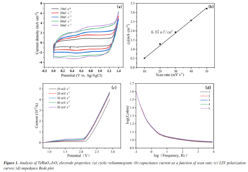
RESULTS AND DISCUSSION Electrode performance analysis The CV curves of the electrodes at various scan rates are displayed in Figure 1a. After five cycles with varying sweep speeds, the electrode retains the matrix characteristics of the ideal capacitance, and the Ti/RuO2-IrO2 anode does the same without redox peaks. Additionally, the area of the Ti/RuO2-IrO2 electrode curve grows with an increase in sweep rate, indicating an increase in the active surface area of the Ti/RuO2-IrO2 electrode, while the cyclic voltammetry curve practically stays the same after each cycle. As a result, the capacity of the electrode for catalytic oxidation is increased, leading to a greater number of active sites and the generation of numerous active compounds.24 The oxidative capability of the active ingredient is inhibited by oxygen evolution reaction (OER), and OER is more difficult to occur when the oxygen evolution potential is higher.24 The LSV curves of the electrodes at various scan rates are displayed in Figure 1c. The oxygen evolution potential of Ti/RuO2-IrO2 is 2.26 V. This effectively suppresses the OER, minimizing its interference during degradation and enhancing the efficiency of the electrode in catalyzing organic oxidation. At frequencies ranging from 0.01 to 10,000 Hz, electrochemical impedance experiments were conducted in the three-electrode setup. Figure 1d demonstrates that in the high frequency range (10-10000 Hz), the electrode impedance mode stays constant as the frequency rises, exhibiting only minor variations as the number of reactions increases. The aforementioned findings demonstrate the extended service life of the electrodes.
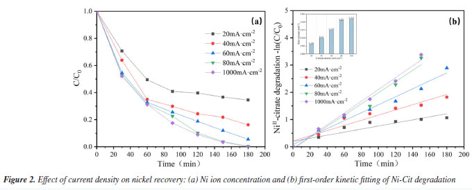
Analysis of influencing factors Effect of current density on nickel recovery performance In statistics, current density is a significantly correlated variable for deposition efficiency.25 This study aims to evaluate the performance of electrocatalytic oxidation combined with electrodeposition for nickel recovery from complexed waste solutions. Typical electroless nickel plating wastewater contains 3.5-7.5 g L-1 of nickel,7 including both complexed and free forms. The effect of current density on nickel ion recovery in complexed waste solution was investigated. Figure 2a shows that for current densities of 20, 40, 60, 80, and 100 mA cm-2, nickel recovery from stainless steel cathodes was 65.5, 83.8, 94.5, 99.6, and 100% after 180 min of electrolysis. The efficiency of nickel ions recovery improved considerably with increasing current density. This is mainly because the anodic potential increases with increasing current density, resulting in improved anodic oxidation. On the one hand, increased current density can produce more active substances and improve the ability of the anode to break complexes; on the other hand, increased current density accelerates electron movement and improves the rate of electrochemical reactions. For the various current densities illustrated in Figure 2a, nickel recovery can be characterized using first-order kinetics and a pseudo-first-order rate constant (k). As shown in Figure 2b, the maximum value of k (0.022 min-1) was reached at a current density of 100 mA cm-2, and the rate constant at this point is more than three times that of a current density of 20 mA cm-2 (0.006 min-1). However, the nickel recovery rate at a current density of 80 mA cm-2 (0.021 min-1) was nearly identical to that at 100 mA cm-2. This is most likely owing to high current densities, which cause extra side reactions (such as oxygen evolution) and lower complex-breaking and recovery efficiency. Nickel reduction on the cathode surface is influenced by competing side processes such as hydrogen precipitation and oxygen reduction, resulting in a drop in nickel reduction efficiency.26
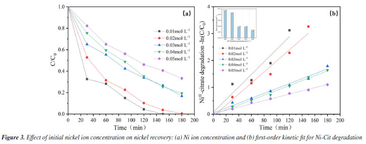
This study also focuses on evaluating the cost of nickel recovery to determine the economic advantages of the system in terms of energy consumption and benefits, depending on market pricing estimates, as shown in Table 1S. The calculation results of energy consumption and economic benefits for nickel recycling have been listed in "Energy consumption and economic benefits of nickel recycling" sub-section presented in the Supplementary Material. A reasonable current density, preferably 80 mA cm-2, was chosen depending on the actual scenario to reduce the overall energy consumption of the process and completely extend the electrode life. Effect of initial Ni ion concentration The EOSE system for Ni-Cit was tested by comparing the recovery of Ni2+. Figure 3a shows the effect of initial NiII-citrate concentration (ranging from 0.01 to 0.05 mol L-1) on the extent of Ni2+ recovery. After 180 min of electrolysis, Ni2+ recoveries were 100, 99.6, 84.5, 81.8, and 69.6%, respectively. As the initial concentration increased, the high concentration of nickel citrate consumed a large number of hydroxyl radicals, resulting in a decrease in anodic complex-breaking efficiency and an indirect effect on cathodic Ni2+ recovery. Longer electrolysis times and higher current efficiencies are required to achieve complete removal, especially at elevated NiII-citrate concentrations.2 As shown in Figure 3b, the pseudo-first-order rate constant (k) significantly decreases as the initial Ni2+ concentration increases from 0.01 to 0.05 mol L-1. The highest rate constant (k = 0.023 min-1) was observed at an initial Ni2+ concentration of 0.01 mol L-1. This value is nearly four times higher than that at 0.05 mol L-1 (0.006 min-1). This is consistent with our previous hypothesis. Furthermore, in terms of the direct electrochemical oxidation mechanism on the anode surface, the higher concentrations of nickel citrate limited the charge transfer at the fixed electrode surface, and the anode was unable to catalyze the oxidation effectively, preventing nickel citrate removal.26
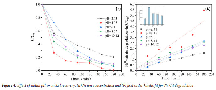
Effect of initial pH It is also known that the pH of the initial solution has a significant impact on oxidative complex breakdown and Ni recovery. The solubility product constant (Ksp) of Ni(OH)2 is 5.48 × 10⁻¹⁶, and the equivalent Ni(OH)2 form is generated when the pH of the solution exceeds 7.87.22 As indicated in Figure 4a, the greatest nickel recovery of 99.6% was obtained at an initial pH of 4.09. The high concentration of active chemicals at the anode surface may break the network, releasing additional Ni2+ into solution and reducing it to metallic nickel bound to the cathode stainless steel.27 Nickel recovery was approximately 90% in the pH range of 6.1-10.12, somewhat lower than in an acidic environment with a pH of 4.09. This could be because in an alkaline environment, more OH- is adsorbed on the anode surface, covering the electrochemically active sites and oxidizing to form O2. This competes with the development of the main reactive groups of the system. However, the recovery of nickel ions was dramatically reduced in an extremely acidic environment at pH = 2.03, with a recovery rate of only 79.5%. The most likely explanation is that H+ reduction is predominantly a cathodic reaction, with excess H+ decreasing the overpotential for H2 release at the starting pH,28 resulting in poor nickel recovery under severely acidic conditions. First-order dynamics with a pseudo-first-order rate constant (k) provide additional description. As indicated in Figure 4b, the maximum value of k (0.024 min-1) was found at pH = 4.09, and as pH increases, the k value decreases. The lowest k value (0.008 min-1) was recorded at pH 2.03, markedly lower than those observed at other pH levels. This provides additional support for the conclusions obtained above. In any case, electrochemical oxidation of Ni-Cit can take place throughout a wide range of initial pH (2.03-10.12) without considerably decreasing the oxidation efficiency of the method. In conclusion, to maximize nickel metal recovery efficiency, an appropriate pH (4.09) was chosen based on the current condition.
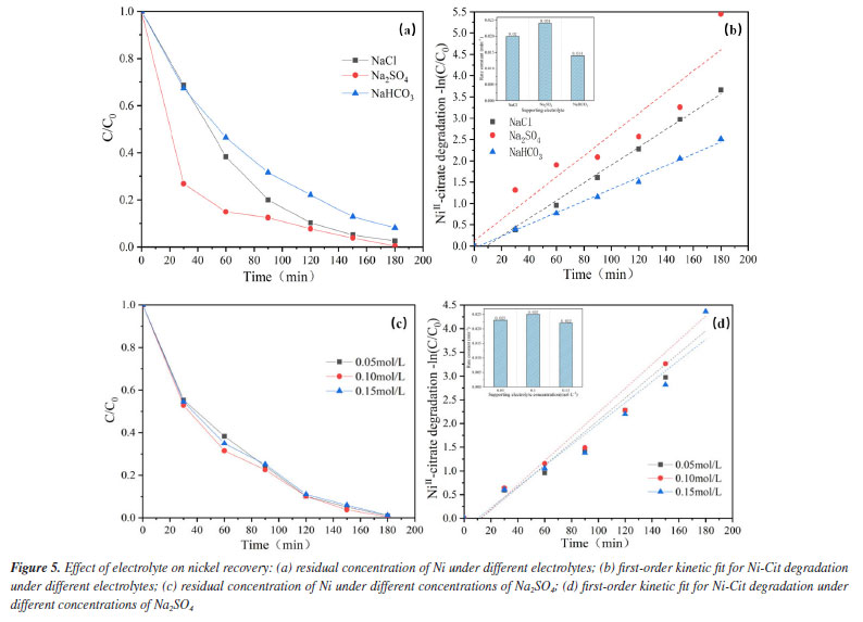
Effect of electrolyte type The electrochemical oxidation process depends a lot on the kind of electrolyte. Some electrolytes release active chemicals that aid in the elimination of pollutants, while others quench free radicals in water and prevent pollutant degradation.29 To evaluate the effect of electrolyte composition on the ability of the EOSE system to treat Ni-Cit, different sodium salts (Na2SO4, NaCl, and NaHCO3) were used as supporting electrolytes (100 mmol L-1 each), and the recovery of nickel metal was compared after 180 min of reaction. As indicated in Figure 5a, the recovery of nickel metal is Na2SO4 > NaCl > NaHCO3. The maximum nickel recovery (99.6%) was achieved using Na2SO4 as the supporting electrolyte. First-order dynamics with a pseudo-first-order rate constant (k) provide additional description. As demonstrated in Figure 5b, the maximum value of k (0.024 min-1) is attained when the supporting electrolyte is Na2SO4, while the minimum value of k (0.014 min-1) is attained when the electrolyte is NaHCO3, the difference between the two is enormous. The explanation for this is most likely because when the electrolyte is NaHCO3, the pH of the aqueous solution is high. Under alkaline conditions, more OH- ions are adsorbed on the anode surface, occupying electroactive sites and undergoing oxidation to O2. This competes with the availability of the active site and reduces the capacity of the EOSE system to degrade nickel citrate. Furthermore, the influence of conductivity on the recovery of nickel ions was examined using varied concentrations of Na2SO4 as the supporting electrolyte. In Figure 5c, the recoveries of Ni2+ after 180 min of electrolysis were 97.4, 99.6, and 96.6% with 50, 100, and 150 mmol L-1 Na2SO4 as supporting electrolytes, respectively. According to the first-order dynamics with a pseudo-first-order rate constant (k), as shown in Figure 5d, the values of k at three different Na2SO4 electrolyte concentrations are 0.023, 0.025, and 0.022 min-1. The concentration of the electrolyte has little effect on the ability of the EOSE system to process nickel citrate. This may be because sulfates consume OH to form SO4-, making it unable to increase the active material by raising its concentration, thereby improving nickel recovery. However, high concentrations of sulfate may cause surface adsorption blockage on the anode, exerting only a minor influence on the on the electrocatalytic performance of the electrode.
Under sulfate electrolyte conditions, the important active species generated during electrolysis are primarily SO4•− and S2O82−. Sulfate (SO42-) acts as an active electrolyte in this process.30 The description of this variation is show in Figure 2S (Supplementary Material). The anode surface of SO42− can undergo direct oxidation to S2O82- (Equation 1) and further activation by radicals or non-radicals to SO4•− (Equation 2).31 SO42- may also be oxidized directly to SO4•− by an electron transfer reaction (Equation 3). At the same time, the reactive radicals (•OH) generated by indirect oxidation at the anode can also contribute to the conversion of SO4•− (Equations 4-6).32 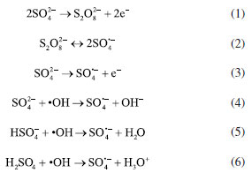 Identification of the Ni-Cit degradation pathway Electrochemical oxidation of Ni-Cit According to earlier research,33 direct electron transfer (DET) and •OH-mediated mechanisms can cause the anodic oxidation of target contaminants. Since they react with •OH at distinct rate constants (1.4 × 10⁶ M−1 s−1 and 4 × 10⁹ M−1 s−1), OA and TA were chosen as probes for direct electron transfer and •OH-mediated reactions, respectively, in light of the possibility that both mechanisms could degrade nickel citrate.22 Figures 6a and 6b show log-linear plots of OA and TA as a function of time, along with the corresponding first-order rate constants for their removal in the Ti/RuO2-IrO2 anode system. The highest removal rates of the two compounds on the Ti/RuO2-IrO2 electrode were 0.004 and 0.005 min-1, respectively. It is demonstrated that DET and •OH-mediated processes occur simultaneously in the electrochemical system with Ti/RuO2-IrO2 as the anode. Based on the TA removal data, the steady-state •OH concentration was found to be 1.25 × 10⁻¹² M.
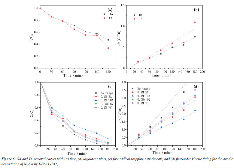
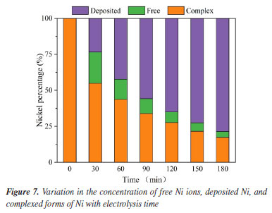
To determine the role of •OH in the breakdown of nickel citrate by Ti/RuO2-IrO2, free radical scavenging tests were conducted to rule out the presence of additional active chemicals. The addition of appropriate amounts of tert-butanol (TBA), ethyl alcohol (EA), ascorbic acid (VC), and 1,4-p-benzoquinone (BQ) trapped hydroxyl radicals, holes, electrons, and superoxide radicals, respectively. Figure 6c shows the change in nickel ions in solution after 180 min of reaction with different trapping agents. It is clear that the addition of tert-butanol has the largest inhibitory effect; nickel recovery with other capture agent additions was nearly comparable to that without the capture agent. The reaction system consists of •OH as the major active species and holes as secondary active species. According to the first-order dynamics with a pseudo-first-order rate constant (k), as shown in Figure 6d, the highest value of k (0.027 min-1) was obtained without the addition of the capture agent, while the lowest value (0.011 min-1) was obtained with the addition of tert-butanol as the capture agent. The electrochemical breakdown of nickel citrate using Ti/RuO2-IrO2 as an anode highlights the significance of •OH. Degradation pathway and degradation mechanism of Ni-citrate The citric acid complex is transformed into numerous intermediates during the electrocatalytic oxidative degradation of Ni-Cit. To discover these intermediates, the electrocatalytic oxidative degradation of nickel citrate was studied. The intermediate products in the electrocatalytic oxidative degradation of Ni-Cit were analyzed using UHPLC-MS on samples collected after 30 and 120 min of electrolysis. The detected intermediates are listed in Table 2S and the possible degradation pathways of nickel citrate are proposed, as shown in Figure 3S (Supplementary Material). Citric acid shows a mass-to-charge ratio (m/z) of 193. All other m/z values arise from its stepwise degradation. One pathway involves hydroxyl radicals attacking the terminal C-COOH group to form 3-hydroxyglutaric acid. Further oxidation produces ketoglutaric acid34 and 3-oxobutyric acid. Acetone is then formed through the loss of the acetate group and is later oxidized to acetic acid. In another pathway, hydroxyl radicals target the terminal C-OH group. This initiates the progressive degradation of citric acid into aconitic, citraconic, mesaconic, itaconic, butenedioic, methacrylic, oxalic, and formic acids. The dominant mechanisms include demethylation and deacetylation reactions. Ultimately, all intermediate products are mineralized into CO2 and H2O. Cathodic nickel metal deposition and analysis of the mechanism The electrodeposition technique is primarily used on the cathodic surface of stainless steel, except for electrocatalytic oxidation of organically complexed ligands at the anode. This study looked at how the shape of nickel in Ni-Cit changed when treated in the EOSE system. Figure 7 shows the concentrations of free nickel ions, complexed nickel, and nickel deposited on the cathode. The free Ni2+ concentration was shown to initially increase during the first 30 min of electrolysis, then gradually decrease and reach zero after 3 h of continuous electrolysis.
The combined effect of direct electrochemical oxidation at the anode and oxidation of indirectly generated •OH breaks the complex state of Ni in the complexed state (NiL2-), as illustrated in Figure 8.
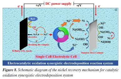
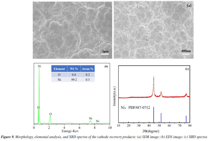
This degradation releases nickel ions into the solution, increasing the concentration of free Ni2+. These ions are then transported to the cathode by the electric field (Equation 7).35 When free nickel ions at the cathode come into contact with OH-, they react to generate Ni(OH)+ compounds on the cathode surface (Equation 8). It can also bind selectively to excess nickel ions, making it easier for Ni to be deposited (Equation 10) and effectively recovering the nickel. These Ni(OH)+ are reduced to Ni(OH)ads in the subcritical state (Equation 9), which are then further reduced to precipitate as monomeric nickel (Equation 11). The hydrogen precipitation reactions on the cathode surface also raise pH of the cathode. (Equation 12). Additionally, Ni(OH)+ compounds are more likely to develop on the cathode surface when the pH rises (Equation 8). These Ni(OH)+ compounds gradually degrade over time, first creating monomeric nickel as well as Ni(OH)2 in the presence of OH- (Equation 13). It is worth noting that the EOSE system continuously creates H+ ions, causing the pH of the cathode to rise due to the hydrogen precipitation reaction, before falling again as the reaction progresses. Thus, Ni(OH)2 is further reduced to create monomeric Ni or NiOOH (Equations 14 and 15).36 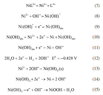 Following electrolysis, the deposition products were collected at the stainless steel cathode and analyzed using SEM-EDS, XRD, and XPS. The SEM images of the deposit are shown in Figure 9a. The deposit is closely arranged in irregular ellipsoidal shapes with rough grains and uneven porosity, corresponding to metallic nickel.37 Meanwhile, Figure 9b shows the EDS spectra of the deposit on the cathode following the electrocatalytic oxidation and electrodeposition reactions. As can be seen, Ni and O are the major components of the deposit, accounting for 99.2 and 0.8%, respectively, indicating that the deposition product on the stainless steel cathode is 99% pure metallic nickel. Physical studies of the recovered compounds were performed using XRD in the temperature range of 10-80 ºC. As shown in Figure 9c, distinct diffraction peaks at 2θ values of 44.80º, 52.75º, and 77.52º correspond to the crystal planes (111), (200), and (220), respectively. These peaks are indexed to the standard monoclinic Ni phase (Joint Committee on Powder Diffraction Standards, JCPDS No. 87-0712),38 reflecting the dominance of nickel and confirming the face-centered cubic structure of the Ni phase.25 No other impurity peaks are observed, indicating that the deposited nickel has high crystallinity.
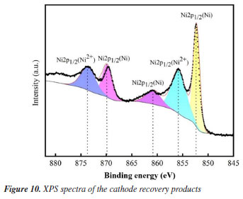
Finally, to understand the putative mechanism of nickel electrodeposition, cathodic deposition was studied using XPS, corrected by the C 1s peak (284.8 eV). Throughout the reaction, the Ni 2p spectra of the product recovered cathodically displayed five peaks, as can be seen in Figure 10. These peaks appeared at 852.30, 855.80, 860.89, 869.61, and 873.73 eV, respectively. The binding energy of Ni(OH)2 is responsible for the two primary peaks for Ni 2p3/2 at 855.80 and Ni 2p1/2 at 873.73, as well as their satellite peak at 860.89 eV.36 The zero-valent nickel peaks are located at 852.30 and 869.55 eV.26 According to the XPS data, the nickel ions in the solution precipitated at the cathode as nickel hydroxide and zero-valent nickel following the electrochemical oxidation of nickel citrate.
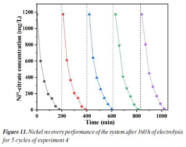
Furthermore, it was discovered that the pH of the solution has a direct impact on the type of nickel that is deposited at the cathode during the electrodeposition reaction. Zero-valent Ni made up the majority of the deposition products at the cathode at pH 3.0 (see Figure 4Sa, Supplementary Material), for pH values higher than 4.0, green Ni(OH)2 is generated (Figure 4Sb). In the meantime, the presence of Ni(OH)2 will hinder the ability of Ni(OH)ads to adsorb Ni ions and lower the recovery efficiency of Ni (Figure 10).2,39 As the reaction proceeds, Ni(OH)2 reacts to create black NiOOH. During the reaction, it was discovered that a single increase in current density did not improve nickel recovery (Figure 3). Instead, this speeds up the initiation of side reactions and the rate of hydrogen generation, resulting in wasted energy. The efficiency of the system is significantly impacted by the mass transfer coefficient and the conductivity of the solution in the electrochemical process. The efficiency of contaminant breakdown and nickel recovery is directly impacted by this phenomenon. The concentration of nickel ions is one of the main parameters influencing conductivity and the mass transfer coefficient.40 To achieve the best Ni recovery, the treatment of Ni-Cit complexation waste streams by the EOSE system must carefully take into account the effects of operational factors such as current density, pH, and initial Ni ion concentration. Electrode life test By checking the long-term deterioration in the performance of the Ti/RuO2-IrO2 anode, the stability of the electrodes was evaluated. First, a 160-h electrolysis was performed on the Ti/RuO2-IrO2 anode. By contrasting the nickel recoveries from the experiment's five cycles. After 160 h of electrolysis, the performance of the Ti/RuO2-IrO2 anode did not decrease, as can be seen in Figure 11, and after five experiment cycles, the nickel recovery was almost constant at 99%. As the anode in the EOSE system for the treatment of metal-organic complexes in the electroless nickel plating waste solution, the results showed the exceptional stability of Ti/RuO2-IrO2.
CONCLUSIONS To mitigate environmental pollution from electroless nickel plating industries and achieve resource recovery of metallic nickel, this study constructed a single-chamber reaction system using a Ti/RuO2-IrO2 mesh electrode as the anode and stainless steel as the cathode to treat nickel-citrate complexes in electroless nickel plating waste liquid. Leveraging the synergistic effect between electrocatalytic oxidation and electrodeposition processes, the impacts of pH, current density, initial Ni2+ concentration, electrolyte type, and electrolyte concentration on nickel recovery were comprehensively analyzed. A series of meticulous experiments confirmed the feasibility of this technology for treating complex waste liquids. Under optimal conditions (current density of 80 mA cm-2, pH 4.05, and 100 mmol L-1 Na2SO4 as the supporting electrolyte), the nickel recovery efficiency reached 99.6%. Notably, higher initial concentrations of Ni-citrate complexes were found to hinder their removal, as Ti/RuO2-IrO2-generated hydroxyl radicals (•OH) were consumed by multiple pollutants. Further investigations revealed that the anodic oxidation of nickel citrate occurs through both direct electron transfer to the anode and indirect oxidation by hydroxyl radicals. Specifically, Ni-Cit complexes are primarily degraded via •OH-mediated oxidation, releasing Ni2+ ions that are reduced and deposited on the cathode surface as Ni0, Ni(OH)2, and NiO phases. These results highlight the significant potential of Ti/RuO2-IrO2 electrodes for practical applications in wastewater treatment. Overall, this study demonstrates a reagent-free treatment method for complex waste liquids that minimizes secondary pollution, requires a moderate budget and simple operation, and consumes minimal energy. The efficient resource recovery of metallic nickel from nickel citrate not only facilitates wastewater remediation but also promotes sustainable development. The findings provide valuable insights into the one-step treatment of electroless nickel plating waste liquids and offer a beneficial integrated approach for practical applications. Based on these lab-scale results, a theoretical foundation is established for further research on resource-oriented treatment of nickel plating waste liquids, contributing to the sustainable and healthy development of the electroplating industry while underscoring the critical significance of environmental protection and resource recycling.
SUPPLEMENTARY MATERIAL Complementary material for this work is available at http://quimicanova.sbq.org.br/, as a PDF file, with free access.
DATA AVAILABILITY STATEMENT All data are available within the text.
ACKNOWLEDGMENTS The authors are very grateful for the guidance and assistance of Prof. Z. G. Xie, J. Yang, and M. Y. Huang, as well as for the assistance of students X. K. Liu, Y. H. Wang, and C. L. Xu in the experiment. Finally, we acknowledge the financial support of the Science and Technology Research Program of the Chongqing Municipal Education Commission (KJZD-M202301301/KJZD-K202101302).
AUTHOR CONTRIBUTIONS All authors contributed to the conception and design of the study. Bingzhao Cui was responsible for methodology, validation, investigation, data curation, writing original draft; Zhigang Xie for resources, writing (review and editing), supervision; Jun Yang for conceptualization, formal analysis, project administration; Xiankang Liu and Yuhan Wang for validation, investigation; Meiying Huang and Chenlin Xu for data calculation.
REFERENCES 1. Pancrecious, J. K.; Ulaeto, S. B.; Ramya, R.; Rajan, T. P. D.; Pai, B. C.; Int. Mater. Rev. 2018, 63, 488. [Crossref] 2. Zhuo, Q.; Xu, X.; Xie, S.; Ren, X.; Chen, Z.; Yang, B.; Li, Y.; Niu, J.; J. Environ. Sci. 2022, 116, 103. [Crossref] 3. Costa, J. M.; da Costa, J. G. R.; Almeida Neto, A. F.; Journal of Water Process Engineering 2022, 46, 102593. [Crossref] 4. Da̧browski, A.; Hubicki, Z.; Podkościelny, P.; Robens, E.; Chemosphere 2004, 56, 91. [Crossref] 5. Lu, Y.; Yang, F.; Chen, S.; Shi, W.; Qi, C.; Peng, G.; Sep. Purif. Technol. 2022, 283, 120142. [Crossref] 6. Lan, S.; Ju, F.; Wu, X.; Sep. Purif. Technol. 2012, 89, 117. [Crossref] 7. Yu, X.; Hou, Y.; Ren, X.; Sun, C.; Wang, M.; Journal of Water Process Engineering 2022, 46, 102577. [Crossref] 8. Scarazzato, T.; Panossian, Z.; Tenório, J. A. S.; Pérez-Herranz, V.; Espinosa, D. C. R.; Desalination 2018, 436, 114. [Crossref] 9. Werber, J. R.; Osuji, C. O.; Elimelech, M.; Nat. Rev. Mater. 2016, 1637. [Crossref] 10. Radjenovic, J.; Sedlak, D. L.; Environ. Sci. Technol. 2015, 49, 11292. [Crossref] 11. Mukherjee, J.; Lodh, B. K.; Sharma, R.; Mahata, N.; Shah, M. P.; Mandal, S.; Ghanta, S.; Bhunia, B.; Chemosphere 2023, 345, 140473. [Crossref] 12. Rong, H.; Zhang, C.; Sun, Y.; Wu, L.; Lian, B.; Wang, Y.; Chen, Y.; Tu, Y.; Waite, T. D.; Chem. Eng. J. 2022, 431, 133230. [Crossref] 13. Sun, Y.; Zhang, C.; Rong, H.; Wu, L.; Lian, B.; Wang, Y.; Chen, Y.; Tu, Y.; Waite, T. D.; J. Hazard. Mater. 2022, 424, 127655. [Crossref] 14. Xu, S.; Yan, N.; Cui, M.; Liu, H.; Environ. Sci. Pollut. Res. 2020, 27, 812. [Crossref] 15. Garcia-Rodriguez, O.; Mousset, E.; Olvera-Vargas, H.; Lefebvre, O.; Crit. Rev. Environ. Sci. Technol. 2022, 52, 240. [Crossref] 16. Li, S.; Dai, M.; Ali, I.; Bian, H.; Peng, C.; Process Saf. Environ. Prot. 2023, 172, 417. [Crossref] 17. Akram, M.; Bano, Z.; Bhutto, S. U. A.; Pan, J.; Uddin, A.; Afzal, M. Z.; Li, L.; Xia, M.; Wang, F.; J. Environ. Chem. Eng. 2024, 12, 112830. [Crossref] 18. Yang, C.; Fan, Y.; Li, P.; Gu, Q.; Li, X. Y.; Chem. Eng. J. 2021, 422, 130032. [Crossref] 19. Wu, L.; Zhang, C.; Sun, Y.; Wang, Y.; Lian, B.; Chen, Y.; Tu, Y.; Waite, T. D.; Chem. Eng. J. 2022, 450, 138188. [Crossref] 20. Zhi, D.; Zhang, J.; Wang, J.; Luo, L.; Zhou, Y.; Zhou, Y.; J. Environ. Manage. 2020, 265, 110571. [Crossref] 21. Zhang, S.; Ma, X.; Du, Y.; Li, Y.; Lin, J.; Chen, S.; Adv. Powder Technol. 2023, 34, 104221. [Crossref] 22. Zhang, J.; Li, Y.; Xie, T.; Cui, Y.; Mao, R.; Zhao, X.; J. Hazard. Mater. 2023, 448, 130601. [Crossref] 23. Guo, L.; Jing, Y.; Chaplin, B. P.; Environ. Sci. Technol. 2016, 50, 1428. [Crossref] 24. Jiang, T.; Guan, W.; Fu, M.; Water Environ. Res. 2022, 94, e10741. [Crossref] 25. Portela, D. G.; Carpanedo, T.; Nepel, D. M.; Costa, J. M.; Mater. Sci. Eng., B 2020, 260, 114611. [Crossref] 26. Liu, H.; Yang, D.; Bao, Y.; Yu, X.; Feng, L.; J. Power Sources 2019, 434, 226754. [Crossref] 27. Yang, S.; Zhao, F.; Li, X.; Cao, B.; Mo, Y.; Chen, D.; Chen, Y.; Journal of Energy Storage 2019, 24, 100799. [Crossref] 28. Jiang, Y.; Zhao, H.; Liang, J.; Yue, L.; Li, T.; Luo, Y.; Liu, Q.; Lu, S.; Asiri, A. M.; Gong, Z.; Sun, X.; Electrochem. Commun. 2021, 123, 106912. [Crossref] 29. Liu, S.; Cui, T.; Xu, A.; Han, W.; Li, J.; Sun, X.; Shen, J.; Wang, L.; J. Hazard. Mater. 2018, 358, 187. [Crossref] 30. Fu, R.; Zhang, P. S.; Jiang, Y. X.; Sun, L.; Sun, X. H.; Chemosphere 2023, 311, 136993. [Crossref] 31. Araújo, K. F.; Barreto, J. P. P.; Cardozo, J. C.; dos Santos, E. V.; de Araújo, D. M.; Martínez-Huitle, C. A.; Environ. Chem. Lett. 2018, 16, 647. [Crossref] 32. Saha, P.; Wang, J.; Zhou, Y.; Carlucci, L.; Jeremiasse, A. W.; Rijnaarts, H. H. M.; Bruning, H.; Environ. Res. 2022, 211, 113057. [Crossref] 33. Babu, D. S.; Mol, J. M. C.; Buijnsters, J. G.; Chemosphere 2022, 288, 132417. [Crossref] 34. Meichtry, J. M.; Quici, N.; Mailhot, G.; Litter, M. I.; Appl. Catal., B 2011, 102, 555. [Crossref] 35. Lan, H.; Li, J.; Sun, M.; An, X.; Hu, C.; Liu, R.; Liu, H.; Qu, J.; Water Res. 2016, 100, 57. [Crossref] 36. Zhang, J.; Djellabi, R.; Zhao, S.; Qiao, M.; Jiang, F.; Yan, M.; Zhao, X.; J. Hazard. Mater. 2020, 394, 122559. [Crossref] 37. Moreira, F. L.; Costa, J. M.; de Almeida Neto, A. F.; Sustainable Chem. Pharm. 2020, 16, 100263. [Crossref] 38. Porto, M. B.; Costa, J. M.; de Almeida Neto, A. F.; Journal of Water Process Engineering 2020, 36, 101250. [Crossref] 39. Zhao, X.; Guo, L.; Hu, C.; Liu, H.; Qu, J.; Appl. Catal., B 2014, 144, 478. [Crossref] 40. Hajdu, J.; Zabrocky, S.; Met. Finish. 2000, 98, 42. [Crossref]
Associate Editor handled this article: Eduardo M. Richter |

On-line version ISSN 1678-7064 Printed version ISSN 0100-4042
Qu�mica Nova
Publica��es da Sociedade Brasileira de Qu�mica
Caixa Postal: 26037
05513-970 S�o Paulo - SP
Tel/Fax: +55.11.3032.2299/+55.11.3814.3602
Free access