
 |
 |
 |
 |
 |
Artigo
| Scanning electron microscopy: an essential tool in the investigation of cement for oil wells |
|
Rafael A. VenturaI; Eduardo J. C. LinsII; Júlio C. O. FreitasI; Antonio E. MartinelliII,* I Instituto de Química, Universidade Federal do Rio Grande do Norte, 59075-000 Natal - RN, Brasil Received: 06/12/2025; *e-mail: eduardo.martinelli@ufrn.br Guest Editor handled this article: Paula M. Jardim Oil well cementing plays a critical role in ensuring zonal isolation, structural integrity, and long-term well safety. Due to exposure to high pressures, temperatures, and chemically aggressive environments, understanding the microstructural behavior of cement systems is essential. This study presents a microstructural analysis of oil well cement slurries using scanning electron microscopy (SEM) as a central tool for the identification and interpretation of hydration products, morphological changes, and the effects of additives and environmental exposure. A wide range of SEM images was collected and organized into a visual reference catalog, including typical hydrated phases such as calcium silicate hydrate (C-S-H), portlandite, ettringite, tobermorite, and xonotlite, as well as carbonation products like calcite and aragonite. The influence of factors such as curing time, temperature, and the incorporation of additives (e.g., silica, palygorskite, polyurethane) was evaluated in terms of morphology, porosity, and matrix integrity. Additionally, energy dispersive X-ray spectroscopy (EDS) was used to complement the morphological analysis with elemental composition data. The results highlight the relevance of SEM as a powerful and versatile technique for the investigation of cementitious materials, offering valuable insights for both scientific research and practical applications in petroleum well cementing under complex and aggressive conditions. INTRODUCTION Portland cement is a hydraulic binder produced by grinding clinker, which consists of silicates, calcium sulfates, and gypsum.1 Its production involves the burning of fossil fuels in large rotary kilns to calcine limestone - a process that emits significant amounts of CO2 and generates notable environmental impacts. Initially, limestone is ground and mixed with clay, forming a fine powder that is transported to silos and subsequently fed into a rotary kiln, where it is calcined at approximately 1450 °C to produce clinker.2,3 After calcination, the clinker is blended with gypsum, which regulates setting time, as well as with pozzolanic materials and calcium carbonate compounds, in order to enhance the performance characteristics of the cement. Although traditionally associated with civil engineering, Portland cement also plays a strategic role in the petroleum industry, particularly in drilling and well abandonment operations. Its application goes beyond structural support, being essential for ensuring zonal isolation, casing stability, and environmental safety.1 In such contexts, cement is exposed to severe operating conditions, including high pressures, elevated temperatures, and chemically aggressive environments, which require materials with long-term durability and reliable performance.4 Therefore, understanding the microstructure and hydration mechanisms of cement becomes fundamental for developing formulations that are more resistant and better suited to these demanding conditions. The hydration of Portland cement involves complex chemical reactions between the silicates and aluminates in the clinker and water. Among the main reactions, the formation of calcium silicate hydrate ((CaO)x(SiO2)γ.H2O) and portlandite (Ca(OH)2) from the hydration of tricalcium silicate (3CaO.SiO2) stands out,5 as represented by:  In addition, the reaction of dicalcium silicate (2CaO.SiO2) contributes to the further formation of calcium silicate hydrate (C-S-H), (CaO)x(SiO2)γ.H2O, at later stages:  The tricalcium aluminate phase (C3A), in the presence of sulfate (typically derived from the gypsum added to the cement), reacts with water to form ettringite6 (3CaO.Al2O3.3CaSO4.32H2O).  These hydration products are directly responsible for the mechanical strength and density of the cementitious matrix.7 The morphological characterization of these phases using scanning electron microscopy (SEM) makes it possible to assess their distribution, crystallinity, and interaction with pores and microcracks, providing critical information on the performance and durability of the cement system in aggressive environments. In the context of the petroleum industry, SEM stands out as a powerful tool for characterizing hydration products and assessing the integrity of the cementitious matrix.8 Its ability to provide high-resolution images with great depth of field enables detailed observation of the morphology, texture, and distribution of phases such as calcium silicate hydrate (C-S-H), portlandite, and ettringite.9,10 Moreover, when combined with complementary techniques such as X-ray diffraction (XRD) and thermogravimetric analysis (TG), SEM provides visual and structural support that enhances the understanding of the underlying physicochemical phenomena. Accordingly, the objective of this article is to demonstrate how the systematic use of SEM represents a key step in the microstructural analysis of cements used in oil well applications, directly contributing to the evaluation of the durability and performance of these materials under various environmental conditions.
EXPERIMENTAL The scanning electron microscope (SEM) used in this study was the VEGA 4 model from Tescan. This is a versatile instrument widely employed in the microstructural characterization of solid materials.11,12 The micrographs presented in this study were obtained by the authors, in collaboration with other researchers from the Cement Laboratory at the Federal University of Rio Grande do Norte (UFRN). By compiling these images and interpretations, the aim is to provide an accessible visual reference for researchers working on cement characterization, supporting the rapid identification of phases and the qualitative analysis of microstructural evolution under different exposure conditions and formulations.
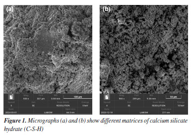
RESULTS AND DISCUSSION The microstructural characterization of the samples was carried out by scanning electron microscopy (SEM) micrographs, enabling detailed analysis of the hydrated phases formed, surface morphology, and the distribution of porosity and microcracks. To better understand the effects of the studied variables, the discussion of the results was organized into four subsections: (i) morphological analysis of standard cement samples; (ii) effects of curing time and temperature on microstructural evolution; (iii) influence of different chemical additives (latex, silica, polymers, graphene) on cement formulations; and (iv) changes observed after sample exposure to environments with high concentrations of carbon dioxide (CO2), simulating aggressive conditions typical of oil wells. Each of these scenarios is discussed individually below, based on the SEM observations and, where applicable, complemented by EDS data. Reference morphology: typical phases in hardened cement In this first stage, micrographs of hydrated Portland cement slurry samples without additives are presented, aiming to illustrate the most recurrent morphological phases observed in conventional cementitious systems. These images serve both as a comparative baseline for modified formulations and as a reference for identifying hydration products in field investigations or laboratory studies. The micrographs clearly reveal the amorphous and irregular morphology of calcium silicate hydrate gel, C-S-H, (CaO)x(SiO2)γ.H2O, which is the predominant phase and the main contributor to the mechanical strength of the system, as shown in Figure 1. Being an amorphous material, C-S-H does not have a well-defined crystal shape, and is instead characterized by a dense, irregular mass.13
The well-defined crystals of portlandite (Ca(OH)2), shown in Figure 2, appear in a hexagonal shape with flat surfaces and are frequently observed in interstitial zones. They can be easily distinguished by their regular, well-defined contours.14
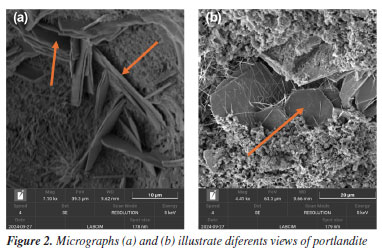
In Figure 2a, it is important to highlight the thinness of the portlandite crystals, which exhibit a lamellar morphology and parallel orientation in some domains. Additionally, the clearly visible hexagonal geometry reinforces the identification of this phase as Ca(OH)2, which is commonly found in hydrated Portland cements.15 Figure 3 shows a cementitious matrix containing several cement phases. The structure of ettringite (3CaO.Al2O3.3CaSO4.32H2O) is easily identifiable by its elongated, acicular shape. This phase is typical of the reaction between aluminates and sulfates during the early stages of hydration.16 These formations exhibit a needle-like morphology, consisting of long, thin crystals frequently arranged in radiating bundles or rosette-shaped clusters.17 The presence of ettringite is more evident in formulations with higher availability of tricalcium aluminate (C3A) and in systems with adequate sulfate content, usually supplied by gypsum addition.
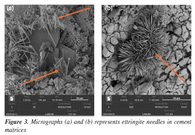
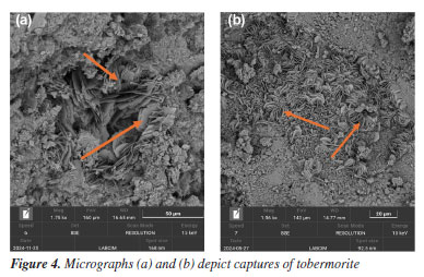
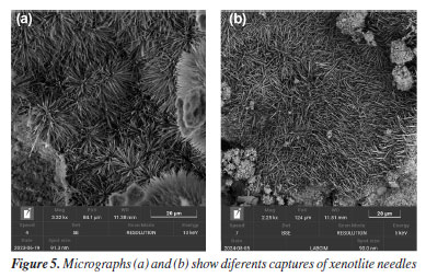
In SEM images, especially in secondary electron (SE) mode, ettringite stands out due to its fibrous texture and three-dimensional growth, often filling pores or cracks within the matrix. Visual identification of ettringite is important, as its excessive formation or recrystallization at later stages may be associated with expansive processes and loss of dimensional stability in the cement slurry. Effects of high temperature and long-term curing on microstructure The exposure of cementitious systems to elevated temperatures, above 110 °C, negatively affects the mechanical properties, particularly the compressive strength, an effect known as mechanical retrogression. There are several approaches to counteract or mitigate this phenomenon, the most traditional being the incorporation of silica-rich materials into the cementitious system. This reduces the Ca/Si ratio, thereby improving both the thermal and mechanical stability of the matrix.18 Studies19 indicate that cement slurry with a Ca/Si ratio below 1.0 exhibit greater mechanical stability under high-temperature conditions, as well as reduced permeability. In this context, the incorporation of silica-rich pozzolanic materials into cementitious systems becomes particularly important for oil well cementing applications exposed to elevated temperatures. Such additions, combined with high temperatures, favor the formation of thermally stable phases such as tobermorite and xonotlite, whose Ca/Si ratios are approximately 0.8 and 1.0, respectively. These phases contribute to the durability and integrity of the cementitious system.20,21 Tobermorite is formed at temperatures between 80 and 150 °C as a result of cement hydration, specifically when C2S (belite) and C3S (alite) come into contact with water. Unlike tobermorite, xonotlite requires even higher temperatures to form, typically occurring in environments above 150 °C. Its formation results from the reaction between portlandite (Ca(OH)2) and silica in the presence of water. In SEM micrographs, tobermorite (Figure 4) is identified by its thin, organized lamellar structures, often forming bundles or plate-like aggregates. Xonotlite, on the other hand, appears as elongated and densely interwoven crystals, resembling floral structures, as seen in Figure 5. These morphologies are distinct from the amorphous C-S-H gel and indicate structural reorganization induced by thermal conditions.
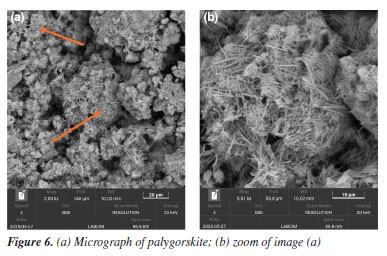
The presence of these phases may be associated with improved thermal stability and reduced porosity. They are also linked to enhanced mechanical properties and long-term performance, depending on the specific exposure conditions.19 Effect of additives in the cement matrix The addition of materials such as clays, polymers, and other compounds can significantly alter the microstructure of the cement slurry. SEM is an essential tool for observing these changes, enabling visualization of additive distribution, dispersion degree, interaction with the cement matrix, and potential alterations in hydration products. These observations help to understand how each additive influences compaction, porosity, and the development of hydrated phases over time. In Figure 6, the characteristic morphology of palygorskite is observed, a hydrated magnesium silicate with a fibrous structure. The micrographs reveal dense bundles of elongated, interwoven fibers, with a disordered preferential orientation, forming a three-dimensional network.22 This needle-like structure with high specific surface area is typical of natural palygorskite and can significantly influence the cement microstructure when incorporated as an additive.23 Its presence within the cementitious matrix tends to modify pore connectivity and the nucleation of hydration products, and it may also act as a physical reinforcement, depending on its dispersion. SEM allows for clear identification of palygorskite fibers, distinguishing them from conventional hydration products based on their organization, dimensions, and surface texture.
Another interesting example of SEM application is the addition of certain polymers to the cementitious matrix (Figure 7). The incorporation of polyurethane (PU) microspheres into cement slurries leads to structural modifications that are clearly observable by scanning electron microscopy. In the analyzed micrographs, the microspheres appear as rounded domains with relatively smooth surfaces, sometimes partially embedded in the cement matrix or, in some cases, split in half.24 SEM enables observation of both the dispersion of these spheres and their interaction with hydration products, particularly at the interface boundaries.
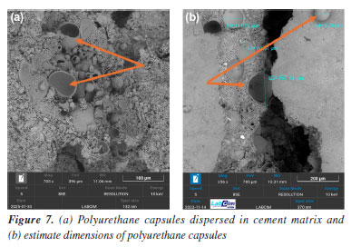
Another important functionality of SEM is the ability to directly measure dimensions such as crystal thickness, pore diameter, fiber length, and particle size.25 In Figure 7, the diameter of the polyurethane capsules is measured. The scale bar inserted in the micrographs, along with the magnification parameters, provides a reliable basis for quantitative analysis, supporting morphological characterization across different formulations.26 These measurements provide confidence in confirming capsule dispersion, homogeneity, and sample population count. PU capsules bring more elasticity and flexibility to the cement paste, a necessary characteristic for steam injection wells, which normally have internal cracks.27 Effects of CO2 exposure (carbonation process) The exposure of cementitious materials to carbon dioxide (CO2) induces chemical and morphological transformations known as carbonation. This process alters the matrix composition, primarily by the reaction of CO2 with portlandite (Ca(OH)2), resulting in the formation of calcium carbonate (CaCO3) and degradation of the cementitious matrix.28 SEM enables the identification of these alterations by revealing morphological changes in the hydrated phases and, more notably, an increased presence of carbonate crystals such as calcite and aragonite. Figures 8 and 9 present examples of cement samples exposed to aggressive CO2-rich environments, with average temperatures of 60-70 °C and a pressure of 2000 psi. This setting aims to simulate supercritical CO2 conditions, which are common in deep petroleum wells, such as those found in Brazilian pre-salt reservoirs.
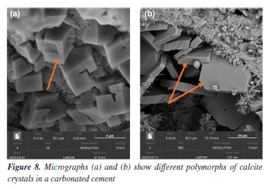
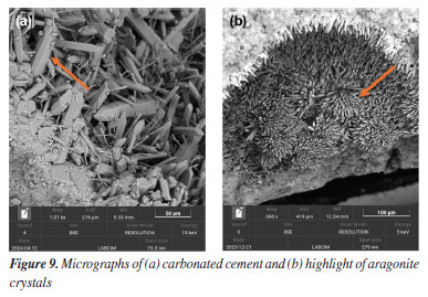
The micrographs shown in Figure 8 reveal the transformation of hydrated phases after CO2 exposure. In Figure 8a, crystals with well-defined cubic morphology indicate the presence of micrometric calcite, one of the main products of carbonation.29 Calcite may also appear in other forms, as seen in Figure 8b, exhibiting flat surfaces and well-defined edges. Figures 9a and 9b show an agglomerate of well-developed prismatic crystals with characteristic morphology of aragonite (CaCO3), a polymorphic form of calcium carbonate. These crystals exhibit rhombohedral terminations and a dense distribution, forming radial arrangements typical of carbonate precipitation.30 The identification of carbonate phases such as calcite and aragonite is critical for assessing degradation in cementitious systems exposed to CO2-rich environments. These phases serve as indicators of carbonation progression and potential loss of matrix integrity. Scanning electron microscopy (SEM) enables precise visualization of their morphology and distribution, supporting failure analysis and the optimization of cement formulations for enhanced durability in aggressive conditions. EDS analyses The energy dispersive X-ray spectrometer (EDS), coupled with SEM, is an essential tool for investigating the composition of cementitious materials.31 By detecting the characteristic X-rays emitted by the elements in the sample, EDS enables the identification and mapping of elements such as calcium, silicon, aluminum, sulfur, and magnesium.32 This analysis complements the morphological data provided by SEM images, helping to distinguish between hydrated phases, additives, unreacted residues, and degradation products, thereby enhancing the understanding of chemical and structural transformations over time.33 Figure 10 presents an example of how EDS supports such investigations. The analyzed sample was exposed to a CO2-rich environment, resulting in the formation of carbonation products.
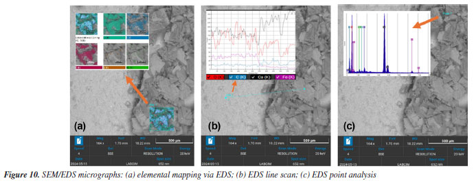
Energy dispersive spectroscopy (EDS) can be employed in three distinct modes, each contributing in a specific way to microstructural investigations.34 In Figure 10a, an EDS elemental mapping is shown, where a previously selected region is analyzed to provide a spatial overview of elemental distribution. This type of analysis enables the visualization of the relative presence of each chemical element. In the example presented, the structures are clearly associated with carbonates, as evidenced by the concentration of calcium, carbon, and oxygen. In Figure 10b, EDS is performed by line scan, composed of a set of points arranged linearly across the sample. This approach is particularly useful for detecting compositional transitions between different regions. In the analyzed example, the scan crosses from a smooth matrix into a zone with more defined particles. The line spectrum reveals a decrease in iron concentration at the interface, accompanied by an increase in carbon and calcium signals, which supports the presence of carbonate compounds. Finally, Figure 10c illustrates point EDS analysis, in which the spectrum is acquired at a single location of interest. This method allows precise elemental characterization of localized structures. In the sample analyzed, the selected point lies on the surface of a suspected carbonate crystal, confirming its typical chemical composition.
CONCLUSIONS Scanning electron microscopy (SEM) has proven to be a fundamental tool for the microstructural characterization of cementitious systems, enabling precise identification of hydrated phases such as C-S-H, portlandite, ettringite, tobermorite, xonotlite, and carbonates. The micrographs obtained demonstrated how variables such as curing time, temperature, the presence of additives, and exposure to CO2 directly influence the morphology and integrity of the cement matrix. The analysis also allowed for high-resolution observation of the interaction between additives and the matrix, as well as the development of degradation products in aggressive environments. The use of SEM, combined with energy dispersive X-ray spectroscopy (EDS), enhanced the understanding of the physical and chemical transformations that occur in cement over time. Thus, this study reinforces that SEM is an indispensable technique in the research and development of materials used in oil well cementing applications.
DATA AVAILABILITY STATEMENT All data generated and analyzed during this study are fully available within the text of the manuscript.
ACKNOWLEDGMENTS The authors would like to thank all the researchers from the Cement Laboratory at Universidade Federal do Rio Grande do Norte (UFRN) who used the SEM to produce images for their investigations, thereby contributing to the extensive image archive, part of which is presented in this article.
REFERENCES 1. Nelson, E. B.; Guillot, D.; Well Cementing, 2nd ed.; Schlumberger: Sugar Land, 2006. 2. Bu, Y.; Du, J.; Guo, S.; Liu, H.; Huang, C.; Constr. Build. Mater. 2016, 112, 39. [Crossref] 3. Ludwig, H. M.; Zhang, W.; Cem. Concr. Res. 2015, 78, 24. [Crossref] 4. Costa, B. L. S.; Freitas, J. C. O.; Araujo, R. G. S.; Oliveira, Y. H.; Santiago, R. C.; Oliveira, F. S.; J. CO2 Util. 2021, 51, 101636. [Crossref] 5. Qi, C.; Manzano, H.; Spagnoli, D.; Chen, Q.; Fourie, A.; Cem. Concr. Res. 2021, 149, 106576. [Crossref] 6. Freitas, C.; Galvão, J. C. A.; Portella, K. F.; Joukoski, A.; Gomes Filho, C. V.; Ferreira, E. S.; Quim. Nova 2009, 32, 913. [Crossref] 7. Gracioli, B.; Varela, M. V. F.; Beutler, C. S.; Frare, A.; da Luz, C. A.; Pereira Filho, J. I.; Rev. Mater. 2017, 22, e11775. [Crossref] 8. Xu, L.; Wang, X.; Qi, Y.; Yuan, C.; Ding, Z.; Xu, R.; Journal of Marine Science and Engineering 2025, 13, 388. [Crossref] 9. Georget, F.; Schmatz, J.; Wellmann, E.; Matschei, T.; J. Microsc. 2024, 294, 105. [Crossref] 10. Scrivener, K.; Snellings, R.; Lothenbach, B.; A Practical Guide to Microstructural Analysis of Cementitious Materials, 1st ed.; CRC Press: Boca Raton, 2016. 11. Ali, A.; Zhang, N.; Santos, R. M.; Appl. Sci. 2023, 13, 12600. [Crossref] 12. Dedavid, B. A.; Gomes, C. I.; Machado, G.; Microscopia Eletrônica de Varredura: Aplicações e Preparação de Amostras; 1a ed.; EDIPUCRS: Porto Alegre, 2007. 13. Thomas, J. J.; Jennings, H. M.; Chen, J. J.; J. Phys. Chem. C 2009, 113, 4327. [Crossref] 14. Scurtu, D. A.; David, L.; Levei, E. A.; Simedru, D.; Filip, X.; Roman, C.; Cadar, O.; Materials 2023, 16, 5313. [Crossref] 15. Galan, I.; Glasser, F. P.; Baza, D.; Andrade, C.; Cem. Concr. Res. 2015, 74, 68. [Crossref] 16. Singh, B. K.; Mahzan, N. S.; Um, W.; ACS ES&T Eng. 2025, 5, 792. [Crossref] 17. Zhang, D.; Li, V. C.; Ellis, B. R.; ACS Sustainable Chem. Eng. 2019, 7, 16310. [Crossref] 18. Richardson, I. G.; Cem. Concr. Res. 2008, 38, 137. [Crossref] 19. Santiago, R. C.; Costa, B. L. S.; Silva, F. P. F.; Medeiros, R. L. B. A.; Nascimento, R. A. B.; Aum, P. T. P.; Freitas, J. C. O.; J. Pet. Sci. Eng. 2021, 199, 108281. [Crossref] 20. Bezerra, U. T.; Martinelli, A. E.; Melo, D. M. A.; Melo, M. A. F.; Oliveira, V. G.; Cerâmica 2011, 57, 150. [Crossref] 21. Wolterbeek, T. K. T.; Cornelissen, E. K.; Hangx, S. J. T.; Spiers, C. J.; Cem. Concr. Res. 2021, 147, 106514. [Crossref] 22. Liu, H.; Tian, Z.; Ma, Y.; Xiang, J.; Sun, X.; Li, J.; Zuo, X.; Case Studies in Construction Materials 2023, 18, e02091. [Crossref] 23. Ventura, R. A.; Carvalho, J. V. A.; Silva, R. R.; Pinto, F. H. S.; Freitas, J. C. O.; Pergher, S. B. C.; Minerals 2025, 15, 637. [Crossref] 24. El Alouani, M.; Saufi, H.; Aouan, B.; Bassam, R.; Alehyen, S.; Rachdi, Y.; El Hadki, H.; El Hadki, A.; Mabrouki, J.; Belaaouad, S.; Ez-Zaki, H.; Barka, N.; Environ. Adv. 2024, 16, 100524. [Crossref] 25. Khan, M. H.; Qiuhong, Z.; Sikandar, M. A.; Zhu, H.; Energy 2025, 330, 136928. [Crossref] 26. Najjar, R.; Akbari, M.; Mirmohseni, A.; Hosseini, M.; J. Taiwan Inst. Chem. Eng. 2018, 93, 1. [Crossref] 27. Anglani, G.; Van Mullem, T.; Tulliani, J. M.; Van Tittelboom, K.; De Belie, N.; Antonaci, P.; Mater. Struct. 2022, 55, 143. [Crossref] 28. Duguid, A.; Radonjic, M.; Scherer, G. W.; Int. J. Greenhouse Gas Control 2011, 5, 1413. [Crossref] 29. Costa, B. L. S.; Freitas, J. C. O.; Santos, P. H. S.; Araújo, R. G. S.; Oliveira, J. F. S.; Melo, D. M. A.; Constr. Build. Mater. 2018, 180, 308. [Crossref] 30. Parker, J. E.; Thompson, S. P.; Lennie, A. R.; Potter, J.; Tang, C. C.; CrystEngComm 2010, 12, 1590. [Crossref] 31. Georget, F.; Wilson, W.; Scrivener, K. L.; Cem. Concr. Res. 2021, 141, 106327. [Crossref] 32. Durdziński, P. T.; Dunant, C. F.; Ben Haha, M.; Scrivener, K. L.; Cem. Concr. Res. 2015, 73, 111. [Crossref] 33. Yuanhua, L.; Dajiang, Z.; Dezhi, Z.; Yuanguang, Y.; Taihe, S.; Kuanhai, D.; Chengqiang, R.; Deping, Z.; Feng, W.; Corros. Sci. 2013, 74, 13. [Crossref] 34. Kleiner, F.; Decker, M.; Rößler, C.; Hilbig, H.; Ludwig, H. M.; Cem. Concr. Res. 2022, 159, 106875. [Crossref] |

On-line version ISSN 1678-7064 Printed version ISSN 0100-4042
Qu�mica Nova
Publica��es da Sociedade Brasileira de Qu�mica
Caixa Postal: 26037
05513-970 S�o Paulo - SP
Tel/Fax: +55.11.3032.2299/+55.11.3814.3602
Free access